projets:fuz:webduino
This is an old revision of the document!
Table of Contents
Webduino Smart
Goals
- [OK] Flash Webduino with different IDEs
- Check Components : pins, photocell, RGB LED, button
- [OK?] Use OTA
Description
- Webduino USB port is only used to power the board, not for upload and monitoring
- The chip is labeled ESP8266MOD by AI Thinker, in fact it is an ESP-12F, same as Wemos d1
- The Board include a photocell, a RGB led and a button.
- Unofficial tutorial in ~english, with how to flash webduino with FTDI
Wiring and flashing
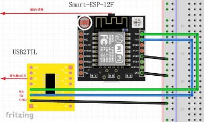
Plug Webduino Smart using FTDI 3.3v module. Webduino and the FTDI must be powered. Webduino is powered through its micro USB port.
         Tx     Rx
ftdi     Rx     Tx     Webduino
         Gnd    Gnd
For flashing, on Webduino Smart connect GPIO 0 to GND. (RGB goes light blue)
For rebooting, on Webduino Smart connect RST to GND
Flashing usual sequence is :
- Set flash position (GPIO0 on GND)
- Power the FTDI and the Webduino
- (RGB goes light blue) Disconnect GPIO 0
- Upload sketch… Webduino should restart in normal mode.
- Or disconnect GPIO 0 and restart using RST or Webduino power
Arduino IDE
Select Board : “Generic ESP8266 Module”
Platformio
Got it to work as a Wemos d1 !
  [env:d1]
  platform = espressif8266
  board = d1
  framework = arduino
Components
I got blink sketch using LED_BUILTIN (2)
RGB LED
/***
   RGB sketch for webduino smart
   Board:   ESP8266

*/

#include <Arduino.h>

// according to https://webduino.io/en/tutorials/smart-01-information.html#on-board-components-and-pins
#define GPIO_GREEN_RGB 12
#define GPIO_BLUE_RGB  13
#define GPIO_RED_RGB 15
#define GPIO_MICRO_SWITCH_BUTTON 4

// https://create.arduino.cc/projecthub/muhammad-aqib/arduino-rgb-led-tutorial-fc003e
void RGB_color(int red_light_value, int green_light_value, int blue_light_value) {
  analogWrite(GPIO_RED_RGB, red_light_value);
  analogWrite(GPIO_GREEN_RGB, green_light_value);
  analogWrite(GPIO_BLUE_RGB, blue_light_value);
}

void showColor(int color) {
  Serial.printf("Color %d\n", color);
  switch (color) {
    case 0:
      RGB_color(255, 0, 0); // Red
      break;
    case 1:
      RGB_color(0, 255, 0); // Green
      break;
    case 2:
      RGB_color(255, 255, 125); // Raspberry
      break;
    case 3: // CYAN
      RGB_color(0, 255, 255); // Cyan
      break;
    case 4: // BLUE?
      RGB_color(255, 0, 255); // Magenta
      break;
    case 5: // GREEN
      RGB_color(255, 255, 0); // Yellow
      break;
    case 6:
      RGB_color(255, 255, 255); // White
    default:
      RGB_color(0, 0, 0); // Disabled
  }
}

void setup() {
  Serial.begin(115200);
  delay(10);
  Serial.println();
  Serial.println(F("Webduino smart RGB sketch: push the micro switch button to loop over colors"));

  pinMode(GPIO_GREEN_RGB, OUTPUT);
  pinMode(GPIO_BLUE_RGB, OUTPUT);
  pinMode(GPIO_RED_RGB, OUTPUT);
}

int color = 0;
void loop() {
  if (digitalRead(GPIO_MICRO_SWITCH_BUTTON) == LOW) {
    Serial.println(F("Button pressed"));
    color = ((color + 1) % 7);
    showColor(color);
    delay(200);
  }
}
Photocell
/***
   Photocell sketch for webduino smart
   Board:   ESP8266

*/

#include <Arduino.h>

// according to https://webduino.io/en/tutorials/smart-01-information.html#on-board-components-and-pins
#define GPIO_PHOTOCELL A0
#define GPIO_MICRO_SWITCH_BUTTON 4

void setup() {
  Serial.begin(115200);
  delay(10);
  Serial.println();
  Serial.println(F("Webduino photocell sketch: push the micro switch button to read photocell values"));
}


void loop() {
  if (digitalRead(GPIO_MICRO_SWITCH_BUTTON) == LOW) {
    Serial.println(analogRead(GPIO_PHOTOCELL)); // values go from 0 for complete blackness to 1024 for full bright light
  }
}
OTA
projets/fuz/webduino.1575409183.txt.gz · Last modified: (external edit)
